AX
PoC Prototyping Workflow Developer
Role: System Designer
Concept: Create a decent prototype in 10 seconds with well-crafted planning documents
In this article, we'd like to introduce you to the PRD-based prototyping workflow we've been building recently. Instead of just explaining and ending the flowchart and policy outlined by the planner in the PRD, it is a prototype that works directly on the actual service screen of today's house.
Before I went into formal development, I wanted to quickly check the customer's reaction with a Proof of Concept (PoC) screen, but each time I drew a new screen, it took me a while to make a prototype. There was only one problem I wanted to solve when creating this workflow. How long would it take to create a PoC and validate a customer response?
First model: Is it possible to create a perfect screen with just the components?
Initially, we created an instruction to create a screen based on the MCP of the pigma frame of the specific screen of the actual prod.
But the result kept showing subtly different parts from the pattern or components of the actual service screen. The colors or typography were slightly off, or the icons were broken. In order to validate customer responses during the PoC phase, we felt that these details needed to be as close as possible to the actual service, so we calibrated the pipeline in two directions.

First calibration, load the actual product as is
It used to be a new way of configuring the actual screen, but it took too long to create the existing screen. And then I thought, Although native apps are difficult, * * * wouldn't a production page distributed on the web be able to fork the actual behavior? * * *
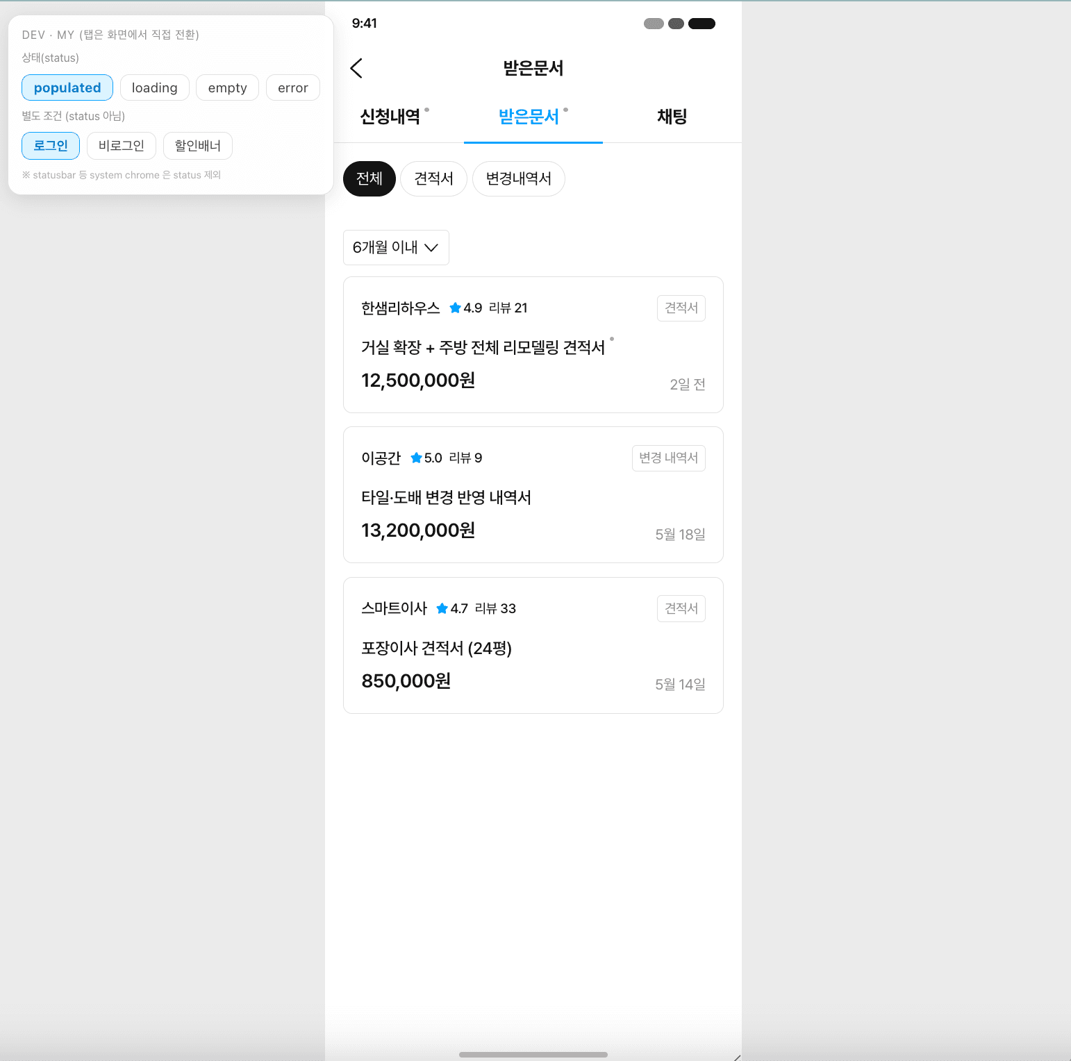
So, I changed the direction and imported a screen that works almost the same as prod by referring to the React · SDUI (Server-Driven UI) configuration implemented in the actual repo, but I cleaned up the legacy tokens remaining in the screen and automatically replaced them with the actual token value of today's house design system (ODS).
In contrast to the ODS catalogue, components with similar names are prevented from being mapped incorrectly and reassembled into components with the actual token value applied.
Second calibration, design diff QA pipeline
No matter how well we mapped tokens and components, we couldn't guarantee that the combined results would look exactly like the real thing. So instead of creating a prototype and finishing it, we added a QA loop to the pipeline that captures the prod screen, contrasts it, and recaptures the broken parts.
The problem that occurs repeatedly by capturing the screen, opening the diff, re-correcting the broken part, and recording the revision history in qa-history is a structure that analyzes the cause and promotes it to a common QA rule.
As I did this, I didn't make the same mistake every time I made a new prototype, and the more I made, the more consistent the structure became.
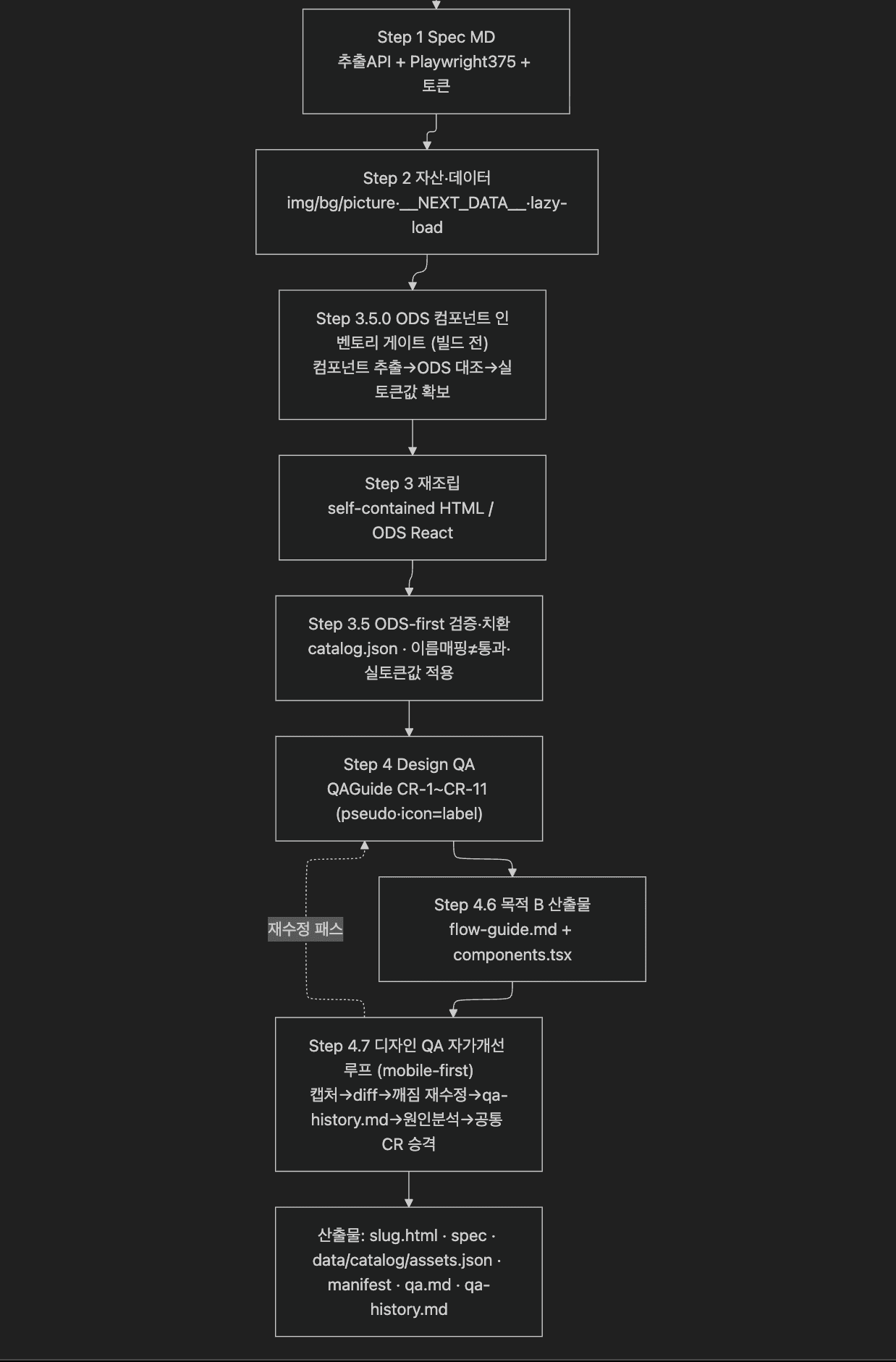
Actual Generated Sample PoC
The screen below is an example of a quick PoC prototype of an idea based on an existing web screen.
It didn't lead to actual product development, but it was a case of meeting a customer with a quickly made prototype and gaining good insights during UT.
(https://lifeservice-form.vercel.app/)
To conclude,
I think the key to this workflow is the ability to quickly see customer responses in context with the actual service before formal development begins.
It is not yet a complete prototype at once, so it has to be modified a few times, but the speed of PoC verification has definitely changed just because the planner can show the flow that was only described in the document as a screen that works straight away.
Especially after adding the design QA loop to the pipeline, we can quickly import that screen into the flow unit and connect the new flow with just one link from the existing web screen. The speed of the work has increased noticeably, and I will continue to refine it.
Latest

Solving problems in the outdated moving brokerage market
2026
Today's House Home Reorganization: From a feed of inspiration discovery to curating navigation
april, 2026
Creator Activity Dashboard
Nov. 2024

Ohouse Tag Editor UX Improvements
Jun. 2024

Browse tab navigation UX revamp
Mar. 2024
Create 10,000 product thumbnails in one click, automatically and in bulk
2026